Introdução
Informações técnicas:
- Não.: T-EPE-0004-00-02 Substitui o nº:A-EPE-2205-04-98
- Distribuição: KL / EP / EPE / EPS / EPT / QS / FL / FM / VTK / VTA / IL / IP / IK
1. Objetivo
Estas instruções descrevem a montagem e desmontagem de conjuntos de unidades (ZKRV) da série de eixos cardan 587/687
2. Área de aplicação
Estas instruções de trabalho são válidas para todos os conjuntos de unidades da série 587 / 687
3. Explicação dos termos
UP = Conjunto de pacote unitário, completo
4. Responsabilidades
Todos os departamentos de serviço que estão envolvidos na desmontagem e montagem ou na substituição de conjuntos completos de unidades são responsáveis pelas atividades realizadas conforme descrito no parágrafo 5.
5. Descrição
Veja os passos abaixo.
6. Notas e comentários:
Nenhum.
7. Documentação:
A documentação das instruções de montagem é mantida no departamento descrito no item 4.
8. Distribuição:
Para distribuição, veja a folha de rosto.
9. Documentos igualmente válidos:
nenhum
10. Apêndices:
nenhum
-
-
A instalação de uma nova UP em eixos propulsores geralmente leva a uma melhoria no estado de balanceamento.
-
Qualquer desgaste que tenha começado a aparecer na junta será eliminado pelo uso de novas UPs.
-
Se em casos individuais a qualidade do equilíbrio G16 será alcançada novamente depende muito do estado de desgaste das estrias na extensão do comprimento.
-
O rebalanceamento do eixo propulsor após a troca das UPs só pode ser evitado quando as seguintes condições forem atendidas:
-
O eixo de transmissão do veículo é um produto genuíno Spicer GWB.
-
O eixo propulsor foi balanceado em seu estado original ou posteriormente a um nível mínimo de G16.
-
Os anéis de retenção dos UP>s anteriores que foram correspondidos em espessura devem ser reutilizados nas mesmas posições.
-
Se as seguintes condições de desmontagem/montagem forem atendidas na troca do UP>s
-
-
-
Antes do início da desmontagem:
-
Para isso, não é permitido usar água de alta pressão, vapor ou produtos químicos agressivos.
-
Numeração contínua das faces individuais dos mancais do eixo propulsor nos jugos relevantes com os números de 1 a 8 conforme o esboço
-
Os anéis de retenção servem para manter a fixação e o movimento axial dos UPs. Eles são ajustados para espessura e não podem ser trocados em hipótese alguma.
-
Portanto, a marcação de cada anel de retenção individual é importante imediatamente após sua desmontagem. Para a marcação, podem ser usadas tiras de fita adesiva, que podem ser marcadas e fixadas nos anéis de retenção.
-
Os anéis de retenção devem receber o mesmo número que o rolamento relevante. vSe os anéis de retenção forem misturados, isso leva a altos valores de desbalanceamento. O ajuste da junta deve ser inspecionado, veja também o Ponto 5.3.6
-
-
-
Insira sabedoria aqui.
-
-
-
Insira sabedoria aqui.
-
-
-
Insira sabedoria aqui.
-
-
-
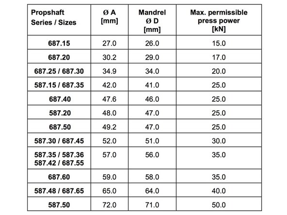
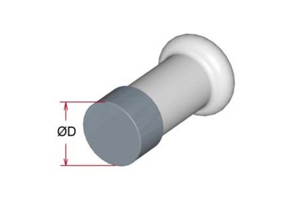
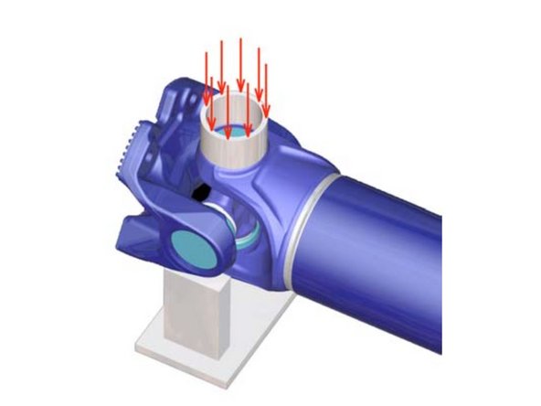
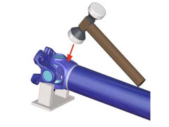
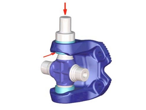
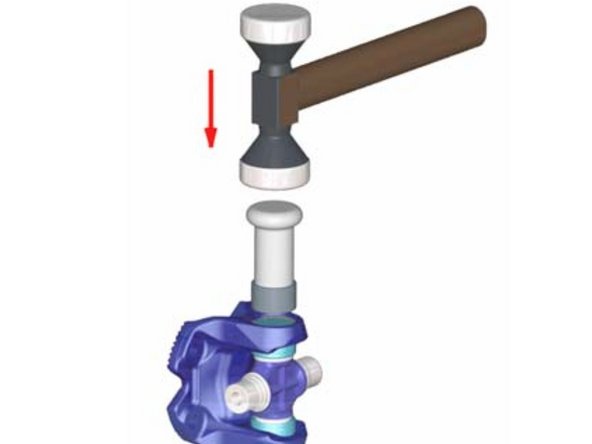
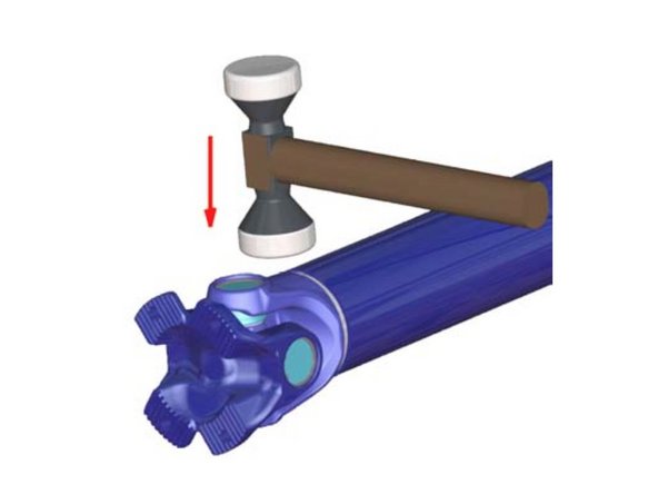
Coloque a junta na bancada de trabalho, coloque o mandril (veja a Fig. 2) no furo do olhal e faça o copo do mancal “assentar” com um golpe forte de martelo. Para dimensões do mandril, veja a Tabela 1.
-
-
-
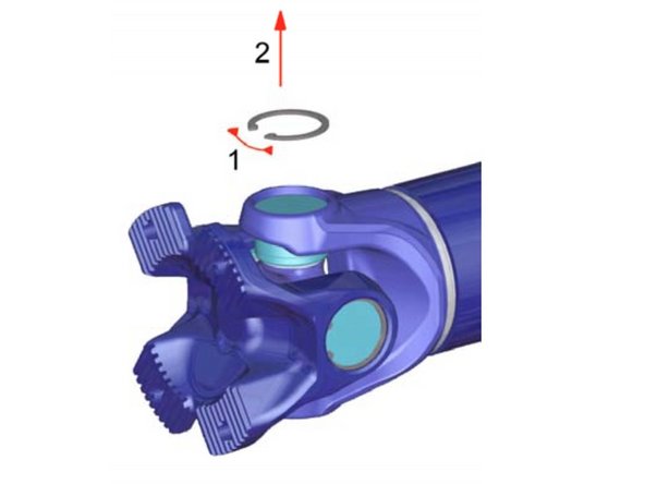
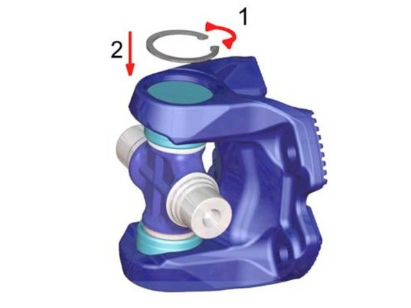
Remova o anel de retenção com um alicate de desmontagem. Gire a junta e remova os anéis de retenção restantes conforme descrito.
-
-
-
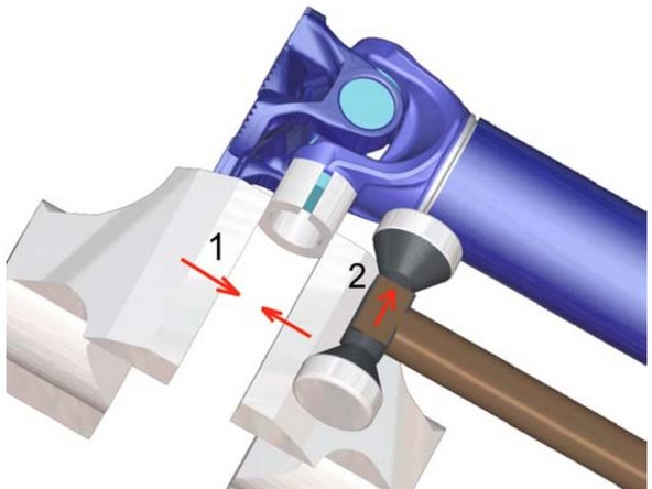
Force o rolamento para fora do garfo do tubo com uma prensa.
-
Além disso, apoie o garfo do flange e force o garfo do tubo para baixo, de modo que a capa do rolamento saia na parte superior do garfo do tubo.
-
Em seguida, gire o eixo propulsor 180° e force para fora o outro copo de rolamento. Ao fazer isso, deve-se prestar atenção para que o jugo do tubo não entre em contato com a cruz do rolamento.
-
-
-
Alternativa -
Nos casos em que não há prensa disponível, os mancais também podem ser removidos por meio de golpes de martelo (metal macio).
-
A lubrificação dos copos de rolamento facilita a saída. Use um torno como suporte.
-
-
-
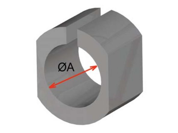
Os rolamentos devem ser desmontados com o dispositivo mostrado à direita (manga de fixação) enquanto fixados em um torno.
-
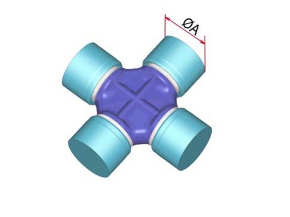
Ø A = Copo do rolamento-Ø
-
-
-
Os rolamentos devem ser retirados do garfo do tubo.
-
Além disso, os rolamentos devem ser mantidos no torno e retirados com leves golpes nas orelhas do garfo.
-
O garfo do flange com a cruzeta do munhão instalada deve ser removido.
-
Os copos de rolamento devem ser removidos do garfo do flange da mesma maneira. Para isso, os copos de rolamento devem ser mantidos com a luva de fixação do dispositivo no torno e puxados para fora por meio de leves golpes de martelo nas orelhas do garfo do flange.
-
Retire a cruzeta do mancal da orelha do garfo do flange. A junta fixa agora está desmontada.
-
A desmontagem da junta deslizante ocorre da mesma maneira que a desmontagem da junta fixa.
-
-
-
A montagem do UP é descrita nas etapas a seguir.
-
-
-
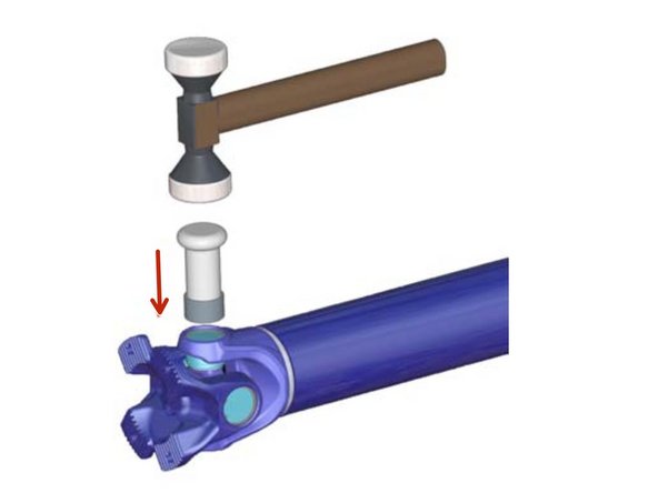
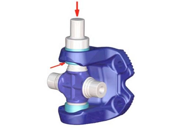
Encaixe o rolamento e pressione até que ele fique visível no lado interno da orelha do garfo (veja a seta).
-
A cruzeta do mancal deve ser colocada no garfo do flange.
-
A pressão de montagem a ser usada para pressionar o rolamento deve ser retirada da tabela 1.
-
-
-
Insira o anel de retenção.
-
Aqui é muito importante manter a ordem correta dos anéis de retenção nos furos das alças.
-
-
-
Pressione o copo do rolamento com a cruzeta do mancal e o copo do rolamento oposto contra o anel de retenção.
-
Os rolamentos são equipados com arruelas de encosto de plástico.
-
Para que as arruelas de encosto não sejam esmagadas na montagem das cruzetas do munhão nas orelhas do jugo, os valores máximos de força de pressão (conforme tabela 1) não podem ser excedidos.
-
-
-
Insira o 2º anel de retenção. De modo que o anel se encaixe exatamente na ranhura.
-
Recomendamos dar uma martelada em um mandril que esteja apoiado no anel de retenção (dimensões do mandril veja tabela 1).
-
-
-
A cruzeta do mancal com o garfo de flange já instalado deve ser inserida nas orelhas do garfo do tubo.
-
O processo restante é o mesmo da montagem da cruzeta do mancal do garfo do flange.
-
“Amenizar” as juntas (através de golpes de martelo nas orelhas do jugo).
-
-
-
Após a conclusão da montagem, as juntas devem ser verificadas quanto à facilidade de movimentação.
-
O ajuste estará correto se os garfos do flange puderem ser movidos manualmente em ambos os planos e não forem puxados para baixo pelo próprio peso quando o eixo propulsor estiver na posição horizontal.
-
Caso a folga seja muito grande ou muito pequena, a configuração da folga da junta pode ser ajustada através do uso do próximo anel de retenção mais fino ou mais grosso. Então é necessário um novo balanceamento do eixo propulsor!
-
A montagem da junta deslizante é realizada da mesma maneira que a da junta fixa.
-
-
-
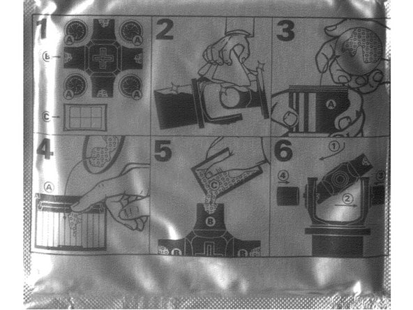
O conjunto da unidade e a almofada de graxa devem ser retirados da embalagem.
-
Os quatro copos de rolamento devem ser removidos da cruzeta do mancal. Os jugos que devem ser montados devem ser limpos.
-
Os reservatórios de graxa nas cruzetas dos mancais devem ser preenchidos com as almofadas de graxa fornecidas.
-
A montagem das UPs pode então ser realizada conforme o Item 5.3 UPs relubrificáveis.
-