Introdução
A Dana Spicer Corporation, Commercial Vehicle Division, apresenta esta publicação para auxiliar na manutenção e na revisão dos eixos de tração simples da Dana Spicer. As instruções contidas abrangem os modelos relacionados. Seu projeto é comum, com diferenças na capacidade de carga. As variações de capacidade são obtidas combinando conjuntos básicos do suporte do diferencial com diferentes alojamentos do eixo, semieixos e equipamento da roda.
Informações gerais
A descrição e as especificações contidas nesta publicação de serviço estarão atualizadas no momento da impressão.
A Dana Spicer Corporation se reserva o direito de suspender ou modificar seus modelos e/ou procedimentos e fazer alterações nas especificações a qualquer momento, sem aviso prévio.
Qualquer referência ao nome da marca nesta publicação é simplesmente um exemplo dos tipos de ferramentas e materiais recomendados para uso e não deve ser considerada como endosso. Os equivalentes, se disponíveis, podem ser utilizados.
Use sempre peças de reposição originais da Dana Spicer.
-
-
Este símbolo é utilizado em todo este manual para destacar os procedimentos onde o descuido ou a não observância dessas instruções especificas pode resultar em ferimentos graves e/ou danos ao componente.
-
Ignorar as instruções, a escolha de ferramentas, os materiais e as peças recomendadas indicados nesta publicação pode colocar em risco a segurança do técnico de manutenção ou do operador do veículo.
-
ADVERTÊNCIA: O não cumprimento dos procedimentos indicados gera um alto risco de ferimentos ao técnico de manutenção.
-
CUIDADO: O não cumprimento dos procedimentos indicados pode causar danos ao componente.
-
IMPORTANTE: Procedimentos altamente recomendados para reparação apropriada desta unidade.
-
OBSERVAÇÃO: As informações adicionais sobre o serviço não abrangem os procedimentos de serviço.
-
DICA: Procedimentos úteis de remoção e instalação para auxiliar na manutenção deste equipamento.
-
DEM: Consulte as especificações do OEM do veículo
-
-
-
Listagem de modelos
-
-
-
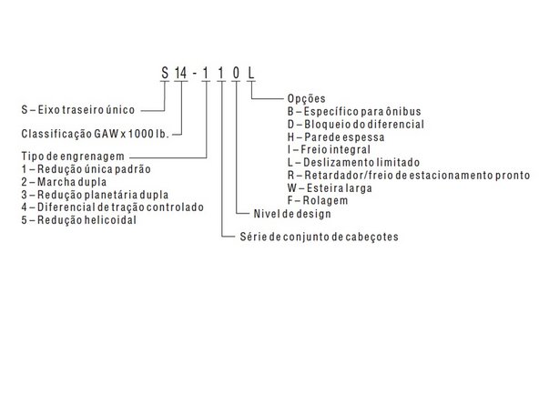
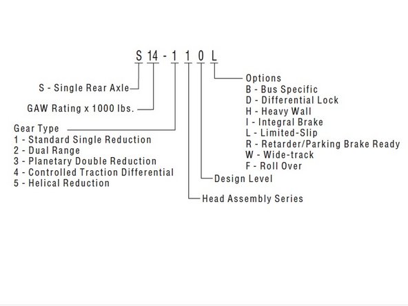
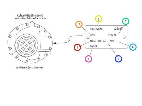
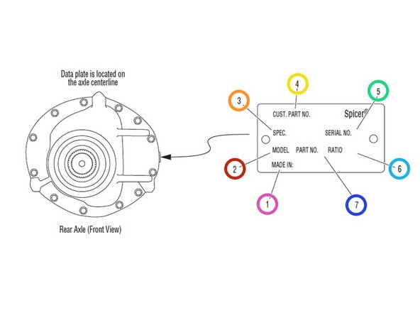
Informações do modelo
-
-
-
1 - País de origem
-
2 - Identificação do modelo do eixo
-
3 - Número da especificação atribuído ao eixo fabricado pela Dana Spicer. Identifica todas as peças do componente do eixo, incluindo requisitos especiais do OEM, tal como garfos ou flanges.
-
4 - O número da peça do OEM atribuído ao eixo integrado
-
5 - O número de série do conjunto do suporte atribuído pela fábrica
-
6 - Relação da engrenagem do eixo
-
7 - Número da peça de produção do conjunto do suporte ou de serviço
-
-
-
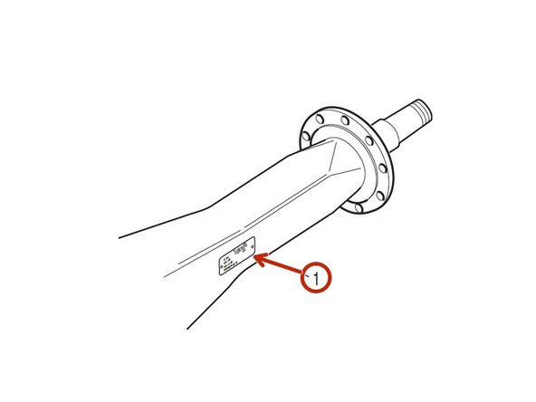
Alojamento do eixo
-
1 - Etiqueta de identificação
-
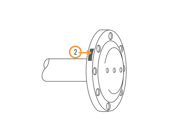
Semieixo
-
2 - Número da peça do semieixo
-
-
-
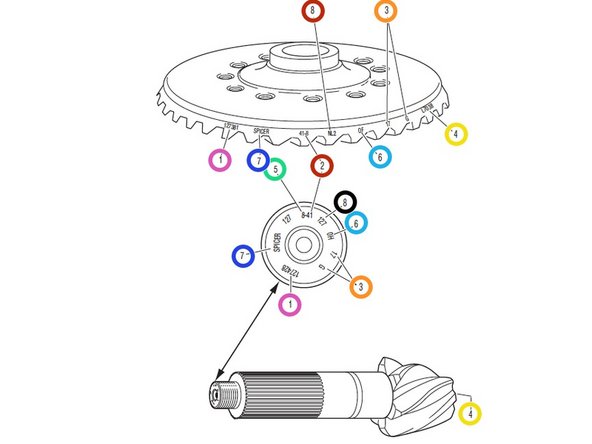
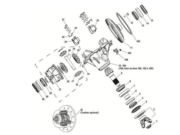
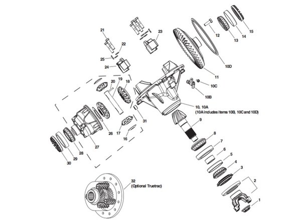
Observação: A coroa dentada e o pinhão de acionamento são peças combinadas e devem ser substituídas em conjuntos. 1 - Número da peça
-
2 - Número de dentes da coroa dentada
-
3 - Números do fabricante
-
4 - Número do conjunto de engrenagem correspondente
-
5 - Número de dentes do pinhão
-
6 - Data de fabricação
-
7 - Indica peças originais Dana Spicer
-
8 - Código de aquecimento
-
-
-
A análise da falha é o processo de determinar a causa original da falha de um componente para evitar que aconteça novamente. Com muita frequência, quando um componente que falhou é substituído sem determinar sua causa, haverá um falha recorrente.
-
Se um alojamento do suporte for aberto, revelando uma engrenagem do anel com um dente quebrado, isso é suficiente para estabelecer o dente quebrado como causa da falha do suporte. Outras peças do suporte devem ser examinadas.
-
Para uma compreensão completa da falha e a possível visão sobre os problemas relacionados, o técnico precisa observar a condição geral do veículo.
-
Não há nenhum benefício quando um componente que falhou vai para uma pilha de lixo com a causa desconhecida. Não é mais irritante para um cliente do que uma falha que se repete.
-
Analisar sistematicamente uma falha para evitar a repetição da ocorrência garante o serviço de qualidade evitando paralisação desnecessária e mais despesas para o cliente.
-
A causa verdadeira de uma falha pode ser determinada melhor se você souber o que procurar, determinando qual a parte do equipamento estava funcionando e aprender com os problemas anteriores. No caso de um eixo traseiro recondicionado, engrenagens não compatíveis podem ter sido instaladas.
-
As oficinas mais bem-sucedidas evitam a repetição da falha do equipamento pelo desenvolvimento de boas práticas de análise de falha. Saber como diagnosticar a causa de uma falha prematura é um dos pré-requisitos de um bom técnico de equipamento pesado.
-
-
-
As cinco etapas a seguir são uma abordagem efetiva para um bom diagnóstico de falhas.
-
Documente o problema.
-
Faça uma investigação preliminar.
-
Prepare as peças para inspeção.
-
Localize a causa da falha.
-
Corrija a causa do problema.
-
-
-
Aqui estão algumas orientações para começar a conhecer uma falha, incluindo as perguntas a fazer:
-
Fale com o operador do caminhão.
-
Analise os registros do serviço.
-
Descubra quando foi a última revisão feita no caminhão.
-
Pergunte: Em que tipo de serviço o caminhão está sendo usado?
-
Pergunte: Essa falha específica já ocorreu antes?
-
Pergunte: Como o caminhão estava funcionando antes da falha?
-
-
-
Você precisa ser um bom ouvinte. Às vezes, sintomas insignificantes ou que não parecem relacionados ao caso podem indicar a causa da falha:
-
Pergunte: O veículo estava operando em temperaturas normais?
-
Pergunte: Os medidores estavam mostrando as variações normais de operação?
-
Pergunte: Havia algum ruído ou vibração anormal?
-
Depois de ouvir, analise os registros de manutenção e reparações anteriores. Se houver mais de um motorista, converse com todos eles e compare suas observações para consistência com os registros de serviço e manutenção.
-
Verifique o número do chassi VIN (Número de Identificação do Veículo) da placa de identificação do veículo, bem como a quilometragem e as horas de funcionamento do veículo.
-
-
-
Essas etapas consistem em inspeções externas e observações que serão valiosas quando combinadas com os resultados do exame das peças.
-
Procure por vazamentos, rachaduras ou outros danos que possam indicar a causa da falha.
-
Faça anotações dos vazamentos óbvios em volta dos bujões e vedações. Um bujão de drenagem ou de abastecimento faltando deveria ser uma causa óbvia para preocupação.
-
Procure por rachaduras no alojamento do suporte (difícil de ver, mas às vezes visíveis).
-
A condição mecânica geral do veículo indica manutenção adequada ou há sinais de negligência?
-
Os pneus estão em boas condições e nos tamanhos corretos?
-
Se equipado com um dispositivo de limitação de torque, ele está funcionando corretamente?
-
Durante a investigação preliminar, anote tudo o que parecer anormal para referência posterior. Os itens que parecem insignificantes agora podem ter mais importância quando os subconjuntos estiverem desmontados.
-
-
-
Depois de uma investigação preliminar, localize a falha e prepare a peça para exame. Na análise da falha do suporte, talvez seja necessário desmontá-lo.
-
Ao desmontar peças e subconjuntos, não limpe as peças imediatamente, pois a limpeza pode destruir alguma evidência.
-
Ao romper o eixo de tração, faça-o de acordo com a maneira recomendada. Minimize qualquer dano adicional ao equipamento.
-
Faça mais perguntas ao examinar o interior do suporte. O lubrificante atende às especificações do fabricante com relação à qualidade, quantidade e viscosidade? Assim que você localizar a peça com defeito, analise os dados cuidadosamente.
-
-
-
Aqui começa o desafio real para determinar a causa exata do defeito. Lembre-se de que não há benefício em substituir uma peça com defeito sem determinar a causa do defeito.
-
Por exemplo, depois de examinar uma peça com defeito e descobrir que a falha foi causada pela falta de lubrificante, você deve determinar se houve um vazamento externo. Obviamente, se houver um vazamento externo, o fato de substituir a engrenagem com defeito não vai corrigir a situação.
-
Outra consideração importante é determinar o tipo específico de falha que pode ser um indicador valioso da causa da falha. As próximas páginas mostram diferentes tipos de falhas e as causas possíveis. Use-as como um guia para determinar os tipos de falhas e a correção dos problemas.
-
-
-
Depois que a causa do problema for determinada, consulte o manual de manutenção apropriado para executar as reparações.
-
-
-
Lave as peças de aço com superfícies polidas ou aterradas com solvente. Existem muitos solventes comerciais adequados disponíveis. O querosene e o óleo diesel são aceitáveis.
-
ADVERTÊNCIA: A gasolina não é um solvente aceitável por causa da sua extrema inflamabilidade. Ela não é segura para ambiente de oficina.
-
Lave as peças fundidas ou outra peças brutas em solvente ou limpe em tanques de soluções quentes usando soluções com base alcalina suave.
-
Observação: Se um tanque de solução quente for usado, certifique-se de que as peças estejam totalmente aquecidas antes de enxaguar.
-
Enxágue completamente para remover todos os vestígios da solução de limpeza.
-
Seque as peças imediatamente com panos limpos.
-
Peças com óleo.
-
Se as peças forem reutilizadas imediatamente: Lubrifique-as levemente. Se as peças serão armazenadas: Coloque uma camada de óleo, envolva-as em papel anticorrosão e armazene em um local limpo e seco.
-
-
-
A inspeção e as reparações no alojamento do eixo são limitadas às seguintes verificações ou reparações.
-
Inspecione visualmente o alojamento do eixo para verificar se apresentam quebras, fendas e rebarbas nas superfícies usinadas.
-
Verifique os prisioneiros e os orifícios do parafusos do suporte quanto à material estranho.
-
Substitua os fixadores danificados. Verifique se há parafusos soltos ou orifícios rosqueados cruzados.
-
CUIDADO: Qualquer dano que afete o alinhamento ou a integridade estrutural do alojamento requer a substituição do alojamento. Não repare curvando ou desempenando. Esse processo pode afetar as propriedades do material e fazer com que falhe completamente sob carga.
-
Verifique todas as vedações e juntas.
-
Observação: Substitua as juntas convencionais por composto de junta de borracha siliconada (incluído em muitos kits de reparação). O composto fornece uma vedação mais eficiente contra infiltração de lubrificação e é mais fácil de remover das superfícies de contato ao substituir as peças.
-
-
-
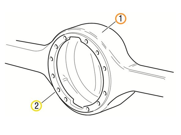
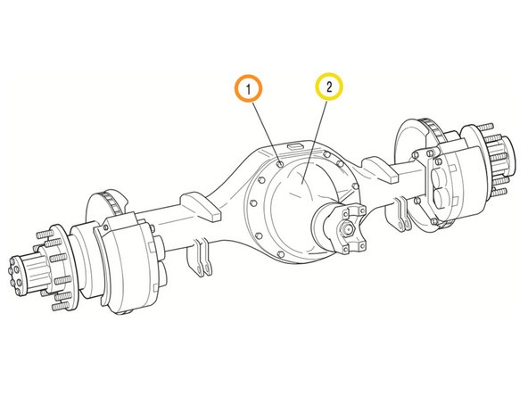
1 - Alojamento do eixo
-
2 - Superfície usinada
-
-
-
Inspecione todas as peças de aço quanto a:
-
Entalhes, degraus ou ranhuras visíveis criadas pelo desgaste.
-
Corrosão ou rachadura ao longo das linhas de contato da engrenagem.
-
Fricção, deformação ou descolorações. Esses são sinais de aquecimento excessivo no eixo e normalmente estão relacionados ao baixos níveis de lubrificação ou às práticas incorretas de lubrificação.
-
-
-
Além disso, inspecione os seguintes itens quanto a danos:
-
Engrenagem diferencial.
-
Rolamentos quanto à encaixes soltos no pinhão de transmissão e os rolamentos do diferencial.
-
Todos os fixadores quanto à cabeças arredondadas, empenamentos, rachaduras ou roscas danificadas.
-
Inspecione as superfícies usinadas das peças fundidas ou maleáveis. Elas devem estar sem fendas, rachaduras, escoriações e desgaste.
-
Procure por aumento dos orifícios perfurados, desgaste nas superfícies usinadas para encaixes do rolamento e fendas ou rebarbas nas superfícies de contato.
-
-
-
Antes de reutilizar um conjunto primário de engrenagens, inspecione os dentes quanto a sinais de desgaste excessivo. Verifique o padrão de contato do dente se há evidência de ajuste incorreto.
-
-
-
1 - Fixador do suporte
-
2 - Conjunto do suporte
-
-
-
Inserir instruções aqui.
-
-
-
Inserir instruções aqui.
-